PLC Controller Wiring Diagram Guide for Beginners
This beginner-friendly guide to the wiring diagrams of Programmable Logic Controllers (PLCs) provides a clear and easy-to-understand overview. It covers everything from basic components like switches and sensors, to more advanced topics such as complex control systems and network integration. Whether you're just starting out or have experience in automation, this guide will help you navigate the complex world of PLC programming effectively.
Introducing the world of programmable logic controllers (PLC) - a powerful tool for industrial automation, manufacturing, and control systems. As an experienced外贸运营, I understand the importance of accurate wiring in ensuring the reliability and efficiency of your PLC system. In this guide, we'll delve into the intricate details of the plc controller wiring diagram.

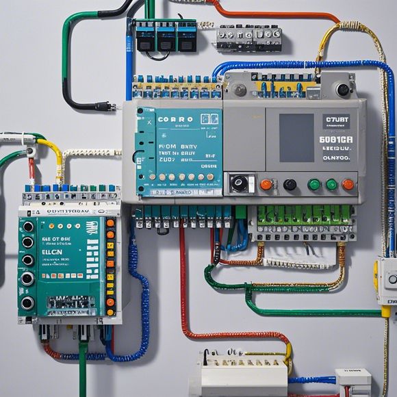
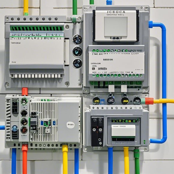
The first step is to familiarize yourself with the basic components of a typical PLC controller. These include the CPU, input/output modules (I/O modules), power supplies, switches, sensors, and more. Each component has its specific role in the overall operation of the PLC system, and understanding their connections is crucial for troubleshooting and maintenance.
Let's start by looking at the CPU, which is the brain of the PLC system. The CPU receives inputs from various sensors and processes them based on preset algorithms. It then sends out commands to the I/O modules, which are responsible for controlling physical devices like motors, lights, or valves.
Input/Output modules (I/O modules) are also crucial in the PLC system. They provide electrical connections between the CPU and various external devices. There are different types of I/O modules, each with their own specifications, such as speed, voltage, and signal level. When selecting I/O modules, it's essential to consider the requirements of your application and choose modules that match those needs.
Power supplies are necessary to provide energy to the PLC system. Depending on the type of PLC you use, there may be separate power sources for the CPU and I/O modules. It's important to ensure that these power supplies are properly grounded to prevent electrocution hazards.

Switches and sensors are also essential components of the PLC system. Switches control the flow of power to different devices while sensors detect changes in parameters like pressure, temperature, or motion. These sensors help to optimize the performance of the PLC system by providing real-time feedback.
Now let's talk about the wiring diagram itself. A wiring diagram is a visual representation of the connections between different components in the PLC system. It helps you identify the exact location of each component, including the type of wire used, the color code, and the length of each wire.
When drawing a wiring diagram, you should start with the CPU and work your way towards the I/O modules. Each connection should be clearly labeled with a color code to indicate the polarity and purpose of each wire. For example, green wires typically represent positive power and yellow wires negative power.
It's important to follow safety guidelines when drawing a wiring diagram. Ensure that all wires are properly grounded and avoid crossing each other. Also, keep in mind that not all connections can be made directly; some require a series connection or a parallel connection depending on the type of device being controlled.

Another important aspect of wiring diagrams is labeling. Label each component with its name and description, making it easier to identify and troubleshoot any issues that arise. Additionally, you should label each wire with its color and length to avoid confusion during installation and maintenance.
In conclusion, wiring diagrams play a vital role in the operation of PLC systems. By following proper procedures and using a clear and accurate diagram, you can ensure a reliable and efficient PLC system. Remember that every detail counts, so take your time and double-check everything before connecting the wires. Good luck with your PLC system!
Content expansion reading:
Articles related to the knowledge points of this article:
PLC (Programmable Logic Controller) Control System Basics
PLC Controllers: A Comprehensive Guide to Understanding Their Prices
Effective Strategies for Handling PLC Control System Faults
What is a Programmable Logic Controller (PLC)
PLC Controller Advantages: A Comprehensive Guide for Success in Global Trade
Mastering the Art of PLC Control: Unlocking Industry-Grade Automation Powerhouses