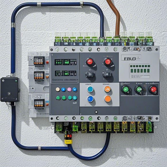
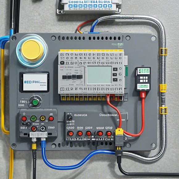
PLC Input and Output Connection Diagram
Sure, I can help with that. Here's a concise summary:The PLC (Programmable Logic Controller) input and output connection diagram is the visual representation of how data flows into and out of your PLC system. It typically includes components such as sensors, actuators, relays, and digital or analog inputs. This diagram shows where each component should be connected to the PLC, and it helps in troubleshooting and programming complex systems.
Introduction:
Hello, everyone! Today, I am excited to introduce you to the essential components of a Programmable Logic Controller (PLC). The purpose of this tutorial is to provide you with an overview of the input and output connections that are used in a PLC system. By the end of this session, you will have a good understanding of how these connections are made and how they contribute to the overall functionality of the PLC.
The first thing we need to discuss is the input connections. An input connection is a way for the PLC to receive data from external sources. In a typical PLC system, there are two types of inputs: digital and analog.
Digital inputs are represented by the letters 'D' in our diagram. These inputs are used for counting and measuring applications. For example, if you want to count the number of times a button is pressed, you would connect a D0 digital input to the button and a D1 digital input to the counter.

Analog inputs, on the other hand, use the letters 'A' instead of 'D'. Analog inputs are typically used for sensors and actuators that generate or measure continuous values like temperature or pressure. For instance, if you have a temperature sensor connected to the PLC, you would connect an A0 analog input to it.
Now let's move on to the output connections. An output connection is another way for the PLC to send data to external devices. Like the input connections, there are also two types of outputs: digital and analog.
Digital outputs are represented by the letters 'Q' in our diagram. Digital outputs can be used for control signals that turn on or off motors or lights. For example, if you want to turn on a light when a button is pressed, you would connect a Q0 digital output to the button and a Q1 digital output to the light.

Analog outputs, on the other hand, use the letters 'M' instead of 'Q'. Analog outputs are often used for controlling valves or other devices that require precise measurements. For instance, if you want to control a valve based on a set point, you would connect an A0 analog output to a PID controller and an A1 analog output to the valve.
In summary, the input and output connections of a PLC play a crucial role in controlling and monitoring various systems. By following the correct wiring instructions provided in this tutorial, you can ensure that your PLC system functions efficiently and accurately. So go ahead and start connecting your wires today!
Content expansion reading:

Articles related to the knowledge points of this article:
PLC (Programmable Logic Controller) Control System Basics
Plumbers Rule! The Role of PLC Controllers in the World of Waterworks
Connecting a PLC Controller to Your Computer
PLC Controllers: A Comprehensive Guide to Understanding Their Prices
Effective Strategies for Handling PLC Control System Faults
PLC Controller Advantages: A Comprehensive Guide for Success in Global Trade