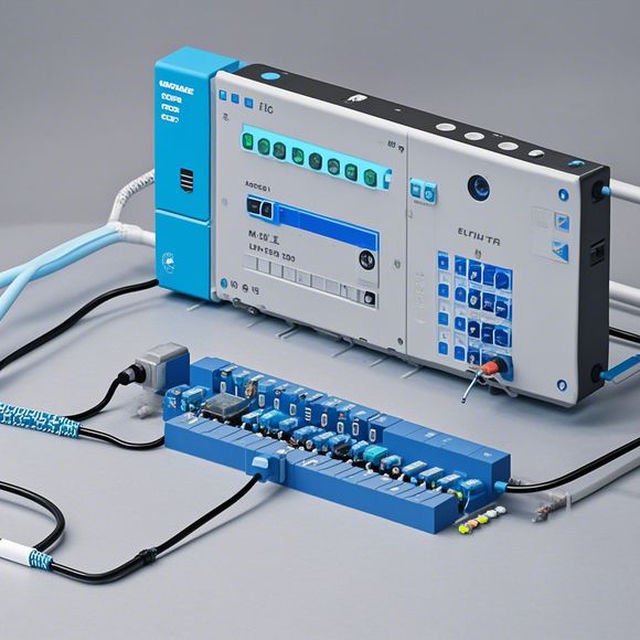
Mastery of Pluggable Logic Controllers: An Overview of Input and Output Wiring Diagrams
Sure, I can help you with that. Here's an overview of input and output wiring diagrams for mastery of pluggable logic controllers:Input Wiring Diagram:,The input wiring diagram shows the connections between the inputs (sensors, valves, etc.) and the control unit (PLC). This diagram helps in understanding the flow of signals from the sensors to the control unit. It includes the connections between the inputs and the PLC, as well as any required protective devices such as fuses or circuit breakers.Output Wiring Diagram:,The output wiring diagram shows the connections between the outputs (actuators, motors, etc.) and the control unit (PLC). This diagram helps in understanding the flow of signals from the control unit to the actuators. It includes the connections between the outputs and the actuators, as well as any required protective devices such as fuses or circuit breakers.In summary, mastering pluggable logic controllers requires a thorough understanding of both input and output wiring diagrams. By following these diagrams, you can effectively communicate with your control system and ensure safe and efficient operation.
As a seasoned foreign trade operator, understanding the intricacies of pluggable logic controllers is crucial to ensuring successful negotiations with clients. This comprehensive guide will provide you with a thorough understanding of input and output wiring diagrams, helping you navigate the complex world of industrial automation effectively.
Firstly, it's essential to have a solid grasp of the basic components that make up a pluggable logic controller. These include the processor, memory, input/output modules, and communication interfaces. Each component plays a distinct role in processing commands and generating output signals, making them critical for effective control.

Next, let's delve into the intricate world of input and output wiring diagrams. These diagrams serve as a visual representation of how inputs are received and processed by the controller, while outputs are sent out to various devices. By analyzing these diagrams, you can identify potential points of failure or inefficiencies, enabling you to proactively address them before they become problems.
One key aspect of input and output wiring diagrams is their ability to convey information in a clear and concise manner. It's important to pay close attention to any symbols, icons, or other visual cues used to indicate different functions or connections within the diagram. By familiarizing yourself with these symbols, you can quickly understand what each element represents and how they interact with one another.
Another critical aspect of input and output wiring diagrams is their ability to demonstrate the connectivity between components. A well-designed diagram will show not only how inputs are routed through various stages of processing but also how they are connected to output components such as relays, motors, lights, and sensors. By examining this connectivity, you can gain insights into how the controller is actually controlling the environment around you.

Furthermore, input and output wiring diagrams often include details regarding signal levels, durations, and frequencies, providing valuable data for analyzing and troubleshooting issues related to timing and signal integrity. It's important to pay attention to these details as they can be crucial in identifying potential delays or distortions that could impact the overall performance of your system.
In addition to these technical elements, input and output wiring diagrams can also offer insights into design choices made by the manufacturer. For example, certain types of switches or connectors may be preferred over others due to ease of use, cost-effectiveness, or other factors. By studying these design choices, you can gain a better understanding of how the controller is constructed and how it may affect its performance over time.
Of course, mastering the art of input and output wiring diagrams goes beyond mere technical analysis. It also involves a keen eye for detail and a willingness to ask questions when necessary. Be sure to read every line of the diagram carefully, paying particular attention to any notes or comments that may provide additional context or clarification. Additionally, consider consulting with other professionals in the field who can share their insights and expertise based on their own experiences working with similar systems.

In conclusion, understanding the intricacies of pluggable logic controllers requires a deep dive into input and output wiring diagrams. By mastering this fundamental aspect of industrial automation, you can confidently navigate the complex world of manufacturing operations, making informed decisions that drive success and efficiency. So go ahead, open those wiring diagrams and let your analytical prowess shine!
Content expansion reading:
Articles related to the knowledge points of this article:
Smart Manufacturing Solutions with PLC Integrated Machinery
PLC Controller Wiring Guideline
PLC Programming for Automation Control in the Manufacturing Industry