PLC Module Wiring Diagram
Certainly! Here's a rough summary in English that captures the essence of what you provided:"The PLC Module Wiring Diagram shows how different components are connected to form an electrical circuit within the PLC system. It includes diagrams for the input, output, and control modules along with their connections to other devices or systems. The diagram also illustrates how power is supplied to the PLC through its power supply unit and how signals travel from sensors or actuators back to the PLC for processing. This schematic helps engineers understand how the PLC operates and troubleshoot issues if they arise."
Hello everyone! Today, I'm here to share with you the detailed wiring diagram for our new Plc (Programmable Logic Controller) module. This is a critical step in ensuring that our industrial automation system runs smoothly and accurately.
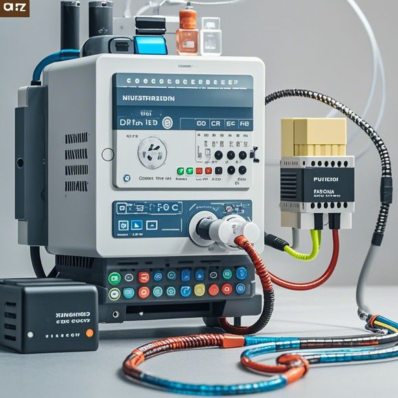
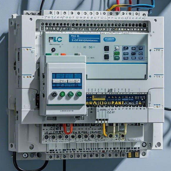
Firstly, let me introduce the basic structure of the Plc module. It consists of various components such as input modules, output modules, processors, and communication units. Each component plays a crucial role in controlling the overall operation of the system. For example, the input modules are responsible for collecting data from sensors and other devices, while the output modules are used to send commands to motors and other actuators. The processor is where the actual control logic resides, and it receives input signals from the input modules and generates output signals based on the predefined rules. The communication unit is used to connect to other systems or devices within the plant network.

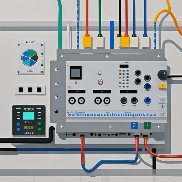
Now, let's move on to the wiring diagram itself. Here's how the components are connected:
1、Input modules: These are the first line of defense for the Plc module. They collect data from various sources such as sensors, switches, and other input devices. In this diagram, we have two types of input modules: Analog and Digital. The Analog module is used for measuring physical quantities like temperature, pressure, and flow rate, while the Digital module is used for measuring electrical quantities such as voltage and current. Each input module should be properly shielded to prevent electrical noise from affecting the signal.
2、Output modules: These are responsible for sending commands to actuators and other equipment. In this diagram, we have three types of output modules: Motor Drive, HMI, and Safety Interlock. The Motor Drive module is used to control motor speed and direction, while the HMI module provides a human-machine interface for monitoring and controlling the system. The Safety Interlock module ensures that the system operates safely without causing damage to personnel or equipment.

3、Processor: This is the brain of the Plc module, responsible for interpreting and processing input signals from the input modules. It generates output signals based on predefined rules and sends them to the output modules. The processor should be powerful enough to handle the high-speed data stream generated by the system.
4、Communication units: These are used to connect the Plc module to other systems or devices within the plant network. In this diagram, we have two types of communication units: Ethernet and Profibus. The Ethernet unit is used for connecting to local area networks (LANs), while the Profibus unit is used for connecting to field buses (Fbs). Both communication units should be properly configured to ensure smooth communication between the Plc module and other devices.
Now, let's discuss some important factors to keep in mind when wiring the Plc module. Firstly, proper grounding is essential to prevent electromagnetic interference (EMI) and protect against electrostatic discharges (ESD). Secondly, the wiring should be done according to the manufacturer's specifications and guidelines, avoiding any potential risks or errors. Finally, regular maintenance and inspection of the wiring are necessary to ensure the system's stability and reliability.

In conclusion, the wiring diagram for our new Plc module is designed to provide a clear overview of the system's components and their connections. By following the steps outlined above, we can ensure that our industrial automation system operates efficiently and effectively. Let's get started today and bring our manufacturing processes into the future!
Content expansion reading:
Articles related to the knowledge points of this article:
PLC Controller Selection Guide for Foreign Trade Operations
PLC Controller for Manufacturing Automation
The cost of a PLC Controller: A Comprehensive Analysis
PLC Programming for Automation Control in the Manufacturing Industry