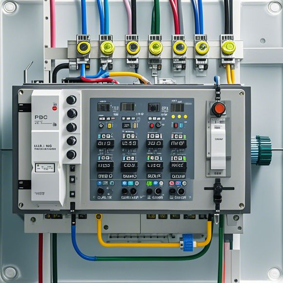
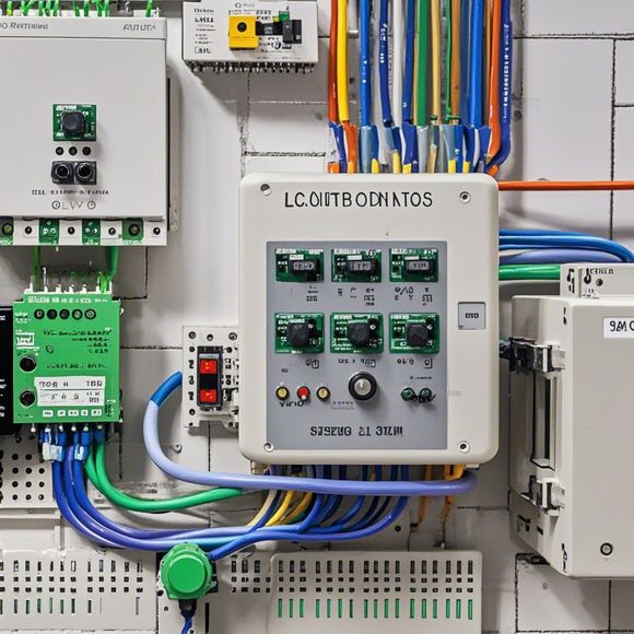
Understanding the Power Line Circuit Diagram (PLC)
In this tutorial, we will delve into the world of Power Line Communication, also known as PLC. This circuit diagram is a crucial tool for those who work in the field of electrical engineering and automation.The Power Line Communication (PLC) system is used to send data from one device to another over a power line. It's an efficient way to transmit large amounts of information without needing additional cabling. The PLC system consists of three main components; the PLC controller, the communication module, and the power supply unit.To understand the PLC circuit diagram, it's essential to comprehend the basic principles behind it. The PLC controller interprets the commands sent by the communication module, which are then converted into electrical signals that can be transmitted over the power line. On the receiving end, these signals are translated back into human-readable instructions.The PLC circuit diagram is a visual representation of the entire setup, making it easier to understand and troubleshoot any issues that may arise. It's a valuable tool for anyone looking to design, install, or maintain a PLC system. With its simple yet comprehensive design, the PLC circuit diagram has become a staple in the world of electrical engineering.
In today's globalized marketplace, understanding and mastering the power line circuit diagram (PLC) is essential for any successful exporter. A well-designed PLC system not only ensures efficient production but also helps in streamlining operations, minimizing downtime, and improving product quality. Here are some key points to keep in mind when interpreting an PLC circuit diagram:
1、Identify the Inputs: Look for the symbols that indicate the various inputs to the PLC. These could include sensors, switches, or other devices that trigger actions based on physical conditions. For example, a temperature sensor reading may trigger an output to adjust the temperature control settings.
2、Determine the Process Sequence: The sequence of events in the PLC program determines how the machine operates. Identify the sequence of commands that control the process flow, such as turning on/off machines, adjusting parameters, and monitoring progress.
3、Analyze Interconnections: Look for lines that connect different elements in the PLC system. These lines can indicate where data flows from one component to another, helping you understand how information is exchanged within the system. For example, if there is a line from a sensor to a motor controller, it means that the sensor's output is used to control the motor's speed.

4、Pay Attention to Outputs: The outputs of the PLC represent the actions taken by the system based on the input signals. Look for lines that lead out of the PLC and indicate what happens next. For example, if an output line leads to a fan, it means that when the fan is activated, it will turn on based on the temperature set by the PLC.
5、Consider Cascading Effects: Some PLC systems have multiple stages of processing. Look for signs that indicate whether a command is passed through additional stages before reaching its final destination. This can help you understand how complex processes are broken down into smaller steps.
6、Read Labels and Notes: Sometimes, instructions are written directly on the PLC components or attached labels. These can provide important insights into the functionality of each device. For example, a label indicating that a particular switch is used to activate a motor might indicate that this switch is crucial to ensuring smooth operation of the motor.
7、Consider Logic Gate Functions: In PLC programming, certain functions are used to process data. For example, an AND gate is used to ensure that only true outputs are sent to the next stage of the process. Knowing these functions can help you understand how decisions are made in the system.
8、Study Error Handling: An PLC system often includes error handling mechanisms to deal with situations where something goes wrong. Look for indicators of these mechanisms, such as alarms or protective circuits that shut down the system in case of failure.

9、Consider Connectivity: If the PLC is part of a larger network, look for lines that indicate connectivity to other systems or devices in the network. This can help you understand how the PLC fits into the broader picture of your business operations.
10、Learn About Programming Languages: While the actual code isn't visible in the diagram, familiarity with popular PLC programming languages like ladder logic, structured text, or function blocks can help you understand how instructions are generated in the PLC program.
Remember, while an PLC circuit diagram provides a visual representation of how the system works, understanding its inner workings requires a combination of knowledge and practice. By following these tips, you can become more confident in interpreting and troubleshooting PLC circuit diagrams.
Content expansion reading:
Articles related to the knowledge points of this article:
PLC Programming for Automation Control in the Manufacturing Industry
PLC (Programmable Logic Controller) Control System Basics
Plumbers Rule! The Role of PLC Controllers in the World of Waterworks
Connecting a PLC Controller to Your Computer
What is a Programmable Logic Controller (PLC)
PLC Controller Advantages: A Comprehensive Guide for Success in Global Trade