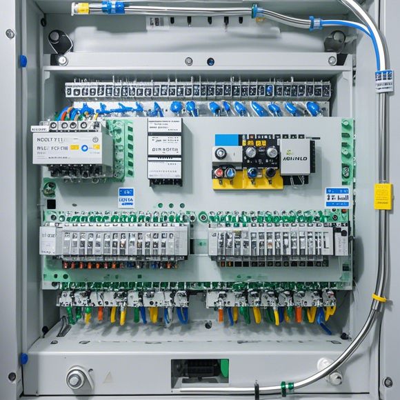
PLC Input/Output Wiring Diagrams for Foreign Trade Operations
Foreign trade activities often require precise and efficient wiring of Programmable Logic Controllers (PLC) to manage the flow of data and control operations. Here's a brief summary:1. **Identify the Requirements**: Before starting any wiring, it’s essential to understand the specific needs of your foreign trade operations, such as how many inputs and outputs are required. This will help in designing a PLC that can handle the necessary tasks.2. **Choose the Right PLC Model**: Based on the requirements identified, choose an appropriate PLC model that can support the necessary number of inputs and outputs. The chosen model should be compatible with the hardware components you plan to use for your trade operations.3. **Design the Wiring Diagram**: Using specialized software, create a detailed wiring diagram that accurately represents the connections between the PLC and various hardware components involved in trading operations.4. **Test the Connections**: Once the wiring is complete, test it to ensure that all components can communicate with each other effectively. This step is crucial as it ensures smooth operation of the PLC and avoids any potential issues during trading activities.5. **Regular Maintenance**: Finally, establish a routine for regular maintenance of the PLC system to ensure it remains functional and efficient throughout the foreign trade operations.By following these steps, you can efficiently and effectively manage the complexities of foreign trade operations using the power of PLC input/output wiring diagrams.
Dear colleagues,

Greetings from the heart of our team! As we delve into the realm of foreign trade operations, it's essential to understand the intricate world of PLC (Programmable Logic Controller) wiring. This is where your meticulousness and attention to detail shine, as you navigate through the labyrinth of wires that make up the foundation of our automation systems.
The PLC is a mastermind in the realm of digital technology, orchestrating the flow of data with an unparalleled precision. Its input/output (I/O) connections are the lifeblood of its operation, providing a pathway through which data is fed back to the control system and processed by the algorithms embedded within.
Imagine a vast landscape teeming with countless variables, each one waiting to be harnessed by the skilled hands of a PLC engineer. Each I/O connection is like a bridge connecting two sides of the equation – the input side, where raw data enters the system, and the output side, where processed information is sent off to perform its magic.
Let's take a walk down this path, exploring the myriad of connections that form the complex web of communication within our PLC systems. The I/O interfaces are the portals to this world, each one unique and capable of handling a vast array of signals. From temperature sensors measuring the heat of metal parts during machining to pressure gauges monitoring the strength of materials under compression, these sensors are our eyes and ears, keeping us informed of the status of our machines and processes.
But wait, there's more! Our PLCs don't just rely on these sensory inputs for their intelligence; they also have powerful output capabilities. These motor controllers, actuators and other devices are designed to respond to commands issued from the PLC, transforming the raw data into actionable results. Whether it's turning valves on or off, adjusting speeds or temperatures, or even programming complex sequences of movements, our PLCs are the masters of transformation.
Now, let's dive deeper into the nuances of this intricate network. The wiring diagrams, much like a map that shows the precise routes taken by soldiers on a mission, provide a roadmap for our PLC systems. Each line represents a connection, and each node stands for a specific device or sensor. The colors and symbols used to label each component add another layer of depth, offering insights into the functionality and reliability of each element.

For example, if you see a blue line leading to a particular relay, it means that the signal from that sensor will activate that particular relay. And if you spot a yellow dot representing a sensor with a fault code, then it's time to investigate and fix the issue before proceeding.
As we navigate through these wiring diagrams, we must remain mindful of the potential hazards lurking around every corner. The wiring should not be tangled or exposed to extreme temperatures, nor should it come into contact with combustible materials. Safety protocols must be followed at all times, and regular inspections and maintenance checks conducted to ensure that our PLC systems continue to perform their duties without fail.
In conclusion, let us not underestimate the significance of our PLC input/output wiring diagrams in shaping the future of our international trade operations. These diagrams serve as the silent guardians of our automated systems, ensuring that every step is executed with precision and efficiency. So let us approach them with reverence, respect their importance, and always strive to improve and enhance their functionality. After all, when it comes to driving growth and success, nothing beats a well-maintained PLC system.
Content expansion reading:
Articles related to the knowledge points of this article:
How to Use a PLC Controller for Your Business
PLC (Programmable Logic Controller) Control System Basics
Plumbers Rule! The Role of PLC Controllers in the World of Waterworks
The Role of Programmable Logic Controllers (PLCs) in Foreign Trade Operations