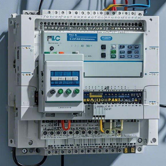
PLC Control Cabinet Wiring Diagrams in English
"The PLC (Programmable逻辑控制器) Control Cabinet Wiring Diagrams in English"This topic is about how to design and draw the wiring diagrams for a Programmable Logic Controller (PLC) control cabinet. In this diagram, it will show you the connection of various components such as sensors, motors, relays, and other devices. The diagram should be detailed enough to clearly indicate the connections between each component, so that you can understand how to operate the PLC system when needed. It's also important to note that these diagrams should be accurate and consistent with the manufacturer's specifications, as they are used to ensure proper functioning of the PLC system.
As a foreign trade operations manager, it is essential to understand the intricacies of PLC (Programmable Logic Controller) control cabinet wiring diagrams. These diagrams play a crucial role in ensuring that the electrical components are correctly connected and functioning as intended. In this guide, we will provide you with an overview of common PLC control cabinet wiring diagrams and their corresponding codes, along with tips on how to interpret them.
Firstly, let us take a look at the most commonly used PLC control cabinet wiring diagram formats. These include the 3-wire and 4-wire configurations, which represent the connections between the PLC board, sensors, actuators, and other electrical components. Additionally, there are other variations such as the 5-wire and 6-wire configurations, which may include additional wires for safety features such as overload protection and grounding.
Now, let’s discuss the common symbols used in these wiring diagrams. For example, the “L” symbol represents a loop, which means that the wire should be connected in a closed loop around the device being controlled. The “O” symbol stands for open, indicating that the wire is not connected or requires further attention. Other frequently used symbols include the “C” for contactors, the “S” for switches, and the “T” for transformers.

When interpreting a PLC control cabinet wiring diagram, it is essential to pay attention to the following points:
1、Identify the type of PLC controller being used. This can be determined by looking for specific model numbers or manufacturer logos on the diagram.
2、Determine the connections required for each electrical component. This includes connecting the power supply terminals, signal inputs, outputs, and other necessary components according to the specifications outlined in the diagram.
3、Follow the appropriate coding conventions when assigning colors and symbols to different components. For example, green may be reserved for input signals, yellow may be used for output signals, and red may indicate alarms or faults.

4、Check for any special instructions or requirements related to safety features, such as overload protection or grounding. These should be followed strictly to ensure that the electrical system is safe and reliable.
In conclusion, understanding PLC control cabinet wiring diagrams is crucial for any foreign trade operations manager. By familiarizing yourself with common symbols and conventions, you can effectively interpret and troubleshoot electrical issues related to PLC systems. Remember to consult relevant technical documentation and consult with experienced professionals whenever needed to ensure optimal performance and safety of your electrical systems.
Content expansion reading:
Articles related to the knowledge points of this article:
PLC Controller Selection Guide for Foreign Trade Operations
Mastering the Art of Plc Controllers: A Comprehensive Guide to Understand and Implement
PLC Controller Wiring Guideline
PLC Programming for Automation Control in the Manufacturing Industry
How to Use a PLC Controller for Your Business
The Role of Programmable Logic Controllers (PLCs) in Foreign Trade Operations