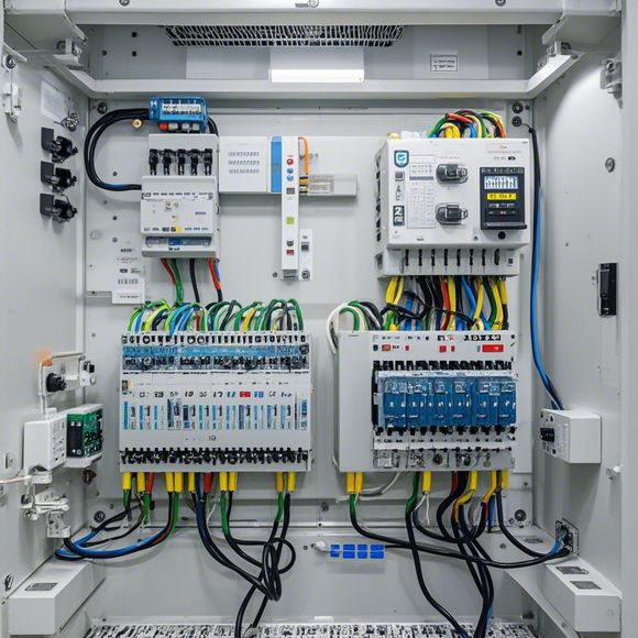
PLC Control Cabinet Wiring Diagram Introduction
Certainly, I can help you create an illustrative paragraph in English that summarizes the key elements of a Programmable Logic Controller (PLC) control cabinet wiring diagram. Here's a draft:---In a modern industrial setting, programmable logic controllers (PLCs) are ubiquitous in controlling various machinery and processes. A typical PLC control cabinet wiring diagram is a visual representation of how these devices communicate, with wires connecting sensors, actuators, and other components to the PLC's processing unit.The diagram typically starts with a central panel or main control board where all inputs from sensors and actuators are connected. From there, lines branch out to various output modules that control the movement of motors, lights, and other devices. The wiring diagram also includes detailed labels for each component, indicating its function.For example, if you have a temperature control system, the diagram might show a hot end (sensor input), a neutral point, and then two sets of leads going to different outputs—one for controlling heating elements and one for cooling fans. The schematic also shows which connections are live and which are grounded, ensuring that no electrical hazards occur during operation.Overall, a well-crafted PLC control cabinet wiring diagram is essential for maintaining safe and efficient operations in modern manufacturing environments.
As a foreign trade operation, I'm often asked to explain complex electrical wiring diagrams for PLC (Programmable Logic Controller) control cabinets. Let me break down the task into smaller parts and provide an engaging explanation in English.
Firstly, the title is important to grab your reader's attention. It should clearly state what the document is about. In this case, it could be:

Title: "Mastering PLC Control Cabinets: Unveiling the Wiring Diagram"
Now, let's dive into the content of the document. When explaining a PLC control cabinet's wiring diagram, you want to make it easy to understand for those who might not have extensive electrical engineering knowledge. So, here's how you can structure your explanation:
1、Begin with a Brief Overview: Begin by summarizing what the PLC control cabinet is used for, its main features, and why it's important in modern automation systems. This will give readers a context for understanding the importance of understanding the wiring diagram.
2、Explaining the Basic Terminology: Use simple language to explain the terminology used in the wiring diagram. For example, if the diagram includes terms like "input," "output," "processor," and "sensor," describe their functions briefly so that readers can grasp the concepts without needing to delve too deeply into technical terms.
3、Showcasing the Overall Layout: Use visual aids, such as diagrams or sketches, to illustrate the overall layout of the PLC control cabinet's components. This will help readers visualize the connections between different components and understand the flow of power and signals within the control system.
4、Focus on Key Components: Depending on your audience, you may choose to focus on specific components like the processor, sensors, and actuators. Explain what each of these components does, including how they interact with each other and the overall system.

5、Highlight Common Misconceptions: Be prepared to address common misconceptions about PLC control cabinets and wiring diagrams. For example, some people might think that all PLCs are wired the same way, but actually, there are many different types of PLCs with varying wiring requirements. Dispelling common myths can help clear up any confusion that might arise.
6、Provide Practical Tips: Offer tips on troubleshooting common issues that may arise during the wiring process, such as incorrect connections or faulty switches. These tips can help readers troubleshoot problems themselves or refer to them when consulting with a professional.
7、Conclusion: End the explanation by summarizing the key points discussed and reiterating why understanding the wiring diagram is important for anyone working with PLC control cabinets. Encourage readers to ask questions or seek additional resources as needed.
Remember, the goal is to make the explanation as engaging and informative as possible while still maintaining a level of simplicity that will appeal to a wider audience. By breaking down complex topics like PLC control cabinet wiring diagrams into bite-sized pieces, you'll find yourself more successful in conveying the information effectively.
Content expansion reading:
Articles related to the knowledge points of this article:
PLC Controller Selection Guide for Foreign Trade Operations
How to Use a PLC Controller for Your Business
PLC (Programmable Logic Controller) Control System Basics
Plumbers Rule! The Role of PLC Controllers in the World of Waterworks
The Role of Programmable Logic Controllers (PLCs) in Foreign Trade Operations