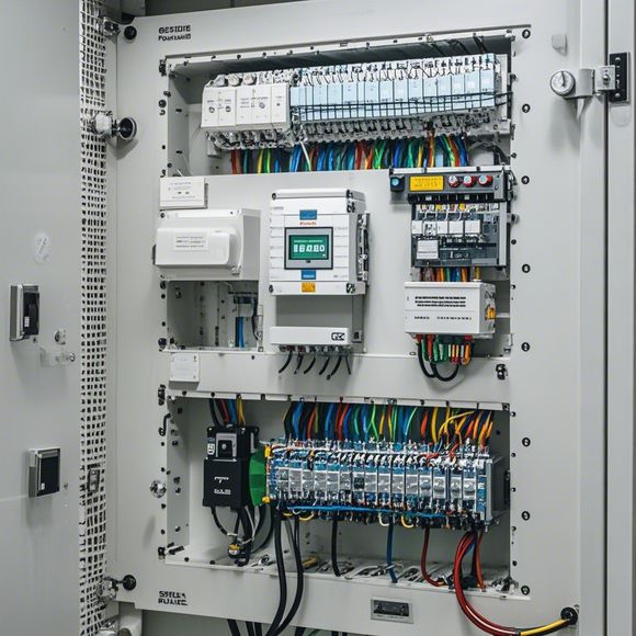
PLC Input-Output Connection Diagram for Factory Automation Systems
The PLC (Programmable Logic Controller) is a critical component in factory automation systems. Its role is to manage the control of various industrial processes. One important aspect of PLCs is their ability to interface with various input and output devices, which can vary widely depending on the specific application.An I/O connection diagram is a visual representation that outlines how these inputs and outputs are connected to the PLC. It helps engineers and technicians understand the flow of data between the system components and ensure smooth operation.In a typical factory automation system, there might be sensors measuring temperature, pressure, or other process variables. These measurements are often sent to the PLC for processing and control actions based on predefined rules. The PLC then sends signals to actuators like motors or valves to adjust the process accordingly.To maintain this system, it's crucial to have a well-designed and maintained I/O connection diagram that clearly shows how all these elements work together. This ensures that the system operates efficiently and reliably, meeting the needs of the factory's production lines.
As a seasoned foreign trade operations professional, I have come across numerous challenges while working with PLC (Programmable Logic Controller) input-output connections. To tackle these challenges and ensure smooth factory automation processes, it's crucial to have an accurate and well-documented PLC input-output connection diagram. This diagram not only helps in understanding the system's internal workings but also ensures that the correct components are connected to the right devices, preventing faulty operations. In this article, I will delve into the key aspects of creating a comprehensive PLC input-output connection diagram for your factory automation needs.
Firstly, let's understand what an PLC input-output connection diagram is. This is a visual representation of how different sensors, actuators, and control devices are interconnected within a PLC system. The diagram typically includes labels, arrows, and other symbols to indicate the electrical connections between various components such as relays, sensors, motors, and switches. It is essential to note that each PLC manufacturer may have slightly different conventions regarding their own input-output symbols. However, most commonly used symbols can be found online or through specialized software tools designed specifically for PLC systems.

Now, let's dive deeper into the key aspects of creating an effective PLC input-output connection diagram. Firstly, you need to start by identifying all the components involved in the automation process. This could include sensors that measure variables like temperature, pressure, and flow rates, actuators that adjust valves or motors, and so on. Once you have identified all the components, you must carefully map them out in the diagram.
The next step is to create a logical flow diagram of the automation process. This involves connecting the sensors, actuators, and other control devices together in a sequence that follows the desired logic. For example, if you want to control the temperature in a factory oven using an input from a thermometer sensor, you would connect the sensor to the PLC and then use a relay to activate the heater when the temperature reaches a certain threshold.
Once you have mapped out the logic, it's time to draw the actual PLC input-output connection diagram. You need to use symbols that are commonly used in the industry for each component and make sure they are clearly labeled. Additionally, arrows should be drawn to show the direction of current flow and power connections between components. Remember to include all the necessary wiring information, such as color codes for power and ground wires, voltage levels, and signal types (e.g. TTL, MODBUS).
It's also important to pay attention to safety considerations during the design process. Ensure that the diagram is designed to minimize hazards, such as overheating or short circuits, that could occur during operation. This means checking for proper grounding and isolation of sensitive electronic components, as well as considering the placement of safety switches or alarms.

In conclusion, creating an accurate and well-documented PLC input-output connection diagram is critical for ensuring successful factory automation processes. By following these steps and paying close attention to safety considerations, you can design a reliable and efficient system that meets your specific needs and requirements. Remember, the key to a successful automation project lies in careful planning, thorough analysis, and meticulous execution.
Content expansion reading:
Articles related to the knowledge points of this article:
How to Use a PLC Controller for Your Business
PLC (Programmable Logic Controller) Control System Basics
The Role of Programmable Logic Controllers (PLCs) in Foreign Trade Operations
Connecting a PLC Controller to Your Computer
PLC Controllers: A Comprehensive Guide to Understanding Their Prices