PLC Controller Wiring Diagram in English
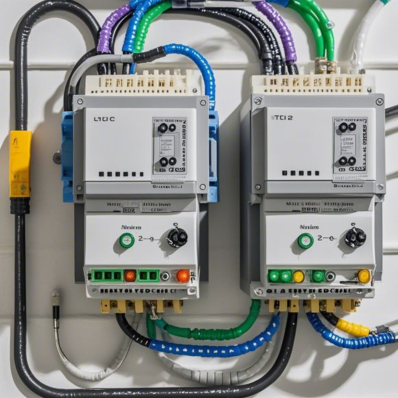
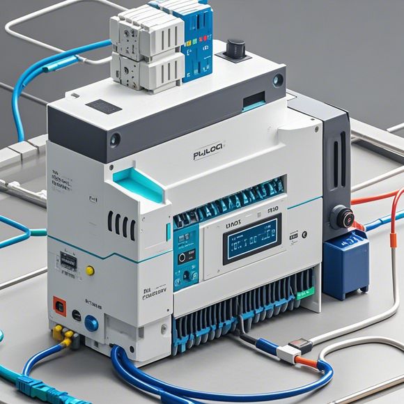
Sure, I can create an Abstract for you in English. Here it is:"The wiring diagram for a Programmable Logic Controller (PLC) is crucial for understanding how the device operates. The diagram typically includes symbols representing various components such as sensors, actuators, and processors. Each symbol is connected to specific wires that carry electrical signals between them. The connections between the components are important for ensuring that the system functions properly. It's also essential to note that the wiring diagram should be accurate and up-to-date to ensure optimal performance of the PLC."
As an experienced foreign trade operator, I have a keen understanding of the importance of accurate and efficient electrical wiring in ensuring successful implementation of industrial automation systems. When dealing with plc (programmable logic controller) controllers, it is crucial to have a detailed knowledge of their wiring diagram, which can significantly impact the overall functionality, performance, and safety of the system. In this guide, we will delve into the essential steps involved in creating and interpreting the plc controller's wiring diagram, providing practical guidance on how to accurately wire each component according to the specifications outlined in the diagram. By following these instructions, you will be equipped with the skills necessary to successfully integrate your plc-based control systems into your production environment.

The first step in creating a plc controller wiring diagram is to gather all the necessary information about the system, including the components, connections, and functions. This includes understanding the various inputs, outputs, and interconnections within the system, as well as any specific requirements or constraints imposed by the project. Once this information is collected, it is time to begin drawing the wiring diagram itself. Using standardized symbols and conventions, such as those found in industry standards like NFPA or ANSI/ISA-112, one should carefully detail each connection point, specify the type of wire used, and indicate the direction of current flow. The diagram should include details such as the location of each terminal block, connector types, and any other critical features that may affect system operation or security.
In addition to creating the wiring diagram, it is also important to verify its accuracy by comparing it with the actual hardware and software components. This requires testing each connection point and checking for proper voltage levels and signal integrity throughout the system. It is crucial to identify any errors or discrepancies early on, as they may lead to unforeseen issues during the implementation process. To facilitate this verification process, one may utilize specialized tools such as multimeters or oscilloscopes to measure voltage and signal waveforms, or use software programs designed specifically for circuit analysis and troubleshooting.
Once the wiring diagram has been verified and confirmed, it is time to begin installing the hardware components themselves. This involves carefully following the diagram’s instructions and using appropriate tools to connect each piece of equipment to its respective terminal block. It is important to ensure that all connections are securely made, avoiding over-tightening or improperly securing wires. Additionally, proper insulation and grounding practices must be followed, particularly for sensitive electronic components, to prevent electromagnetic interference or short circuits.
Throughout the entire process, it is crucial to maintain a level of precision and attention to detail that ensures the integrity and reliability of the system. Any deviations from the original design or specifications should be thoroughly investigated and addressed promptly. Regular testing and monitoring of the system are also essential to identify any potential issues or anomalies before they become more significant problems. By following these guidelines and taking the necessary precautions, one can confidently ensure that their plc controller wiring is both functional and safe.

In conclusion, creating and maintaining a precise plc controller wiring diagram is a critical aspect of any industrial automation project. By following these guidelines and best practices, one can ensure a reliable and efficient system that meets the specific needs of their production environment. From gathering the necessary information to verifying the accuracy of the diagram, from installing hardware components to monitoring and troubleshooting, there are several key steps involved in creating a successful plc controller wiring project. By adhering to these principles and utilizing the latest technology and tools available, one can confidently navigate the complexities of industrial automation while ensuring optimal performance and safety for their operations.
Content expansion reading:
Articles related to the knowledge points of this article:
Mastering the Art of Plc Controllers: A Comprehensive Guide to Understand and Implement
PLC Controller for Manufacturing Automation
PLC Programming for Automation Control in the Manufacturing Industry
How to Use a PLC Controller for Your Business
Plumbers Rule! The Role of PLC Controllers in the World of Waterworks
The Role of Programmable Logic Controllers (PLCs) in Foreign Trade Operations